 English
 русский
 Español
-
 Wheel Hub Bearings
 -
 Wheel Hub Bearings
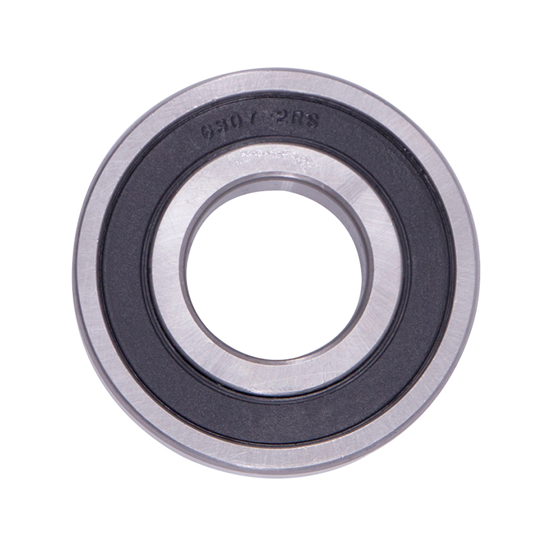
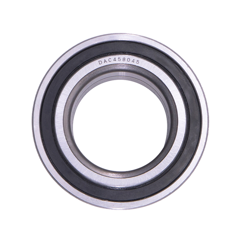
DAC387436 DAC458045 Hub Deep Groove Ball Car Wheel Bearing
-
 Spherical Bearings
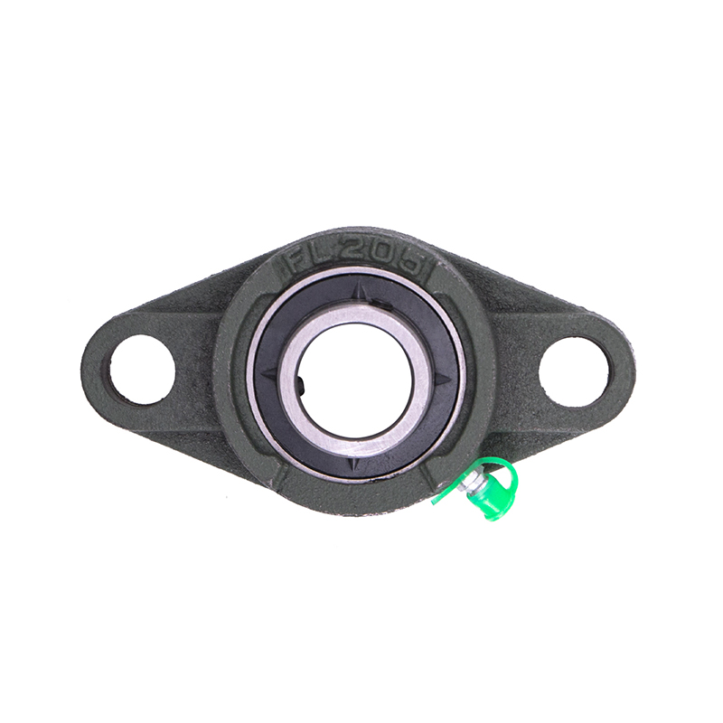
FL204 FL205 FL206 Stainless Steel Pillow Block Bearing
-
 Spherical Bearings
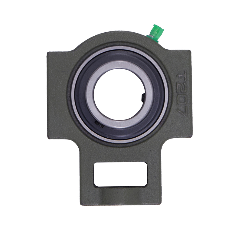
T204 T207 UC204 High Speed Insert Pillow Block Bearing
-
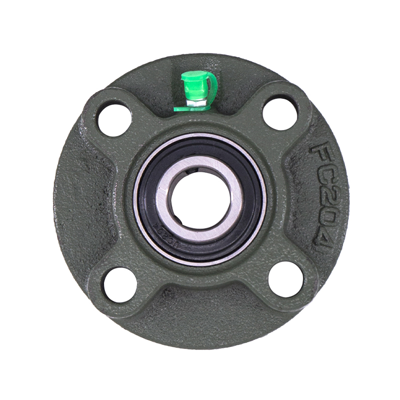 Spherical Bearings
FC204 F210 Auto Wheels Bike Pillow Block Bearing
-
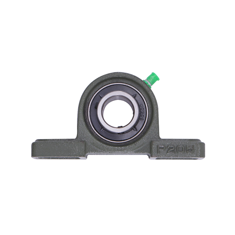 Spherical Bearings
P207 206 205 203 High Precision Wheel Pillow Block Bearing
-
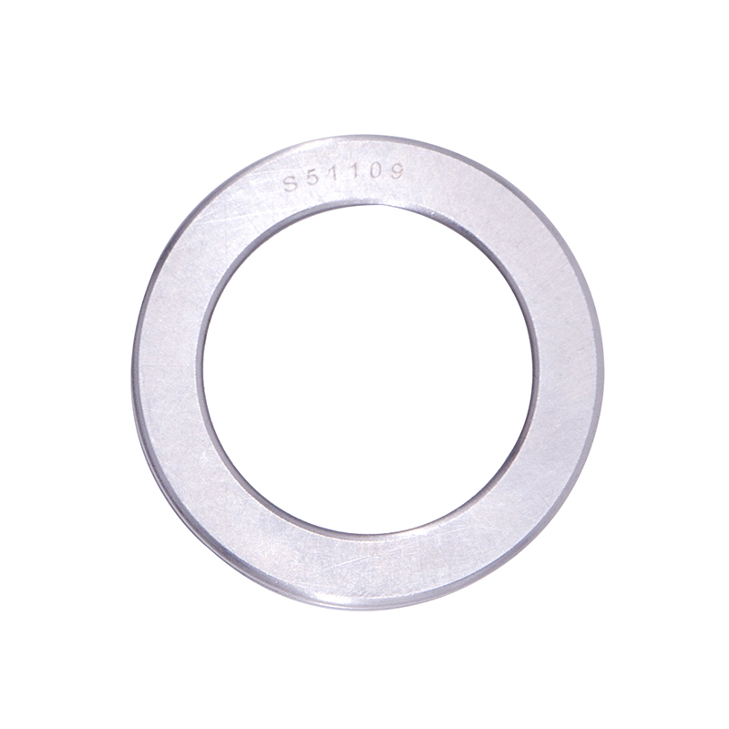 Thrust Roller Bearings
S51100 S51107 S51109 Car Wheel Plain Thrust Ball Bearing
-
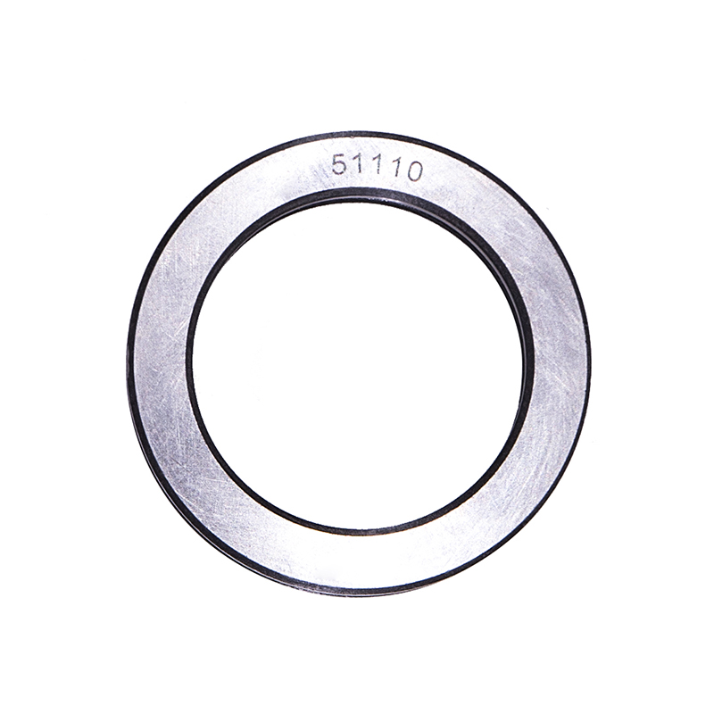 Thrust Roller Bearings
51110 51107 51104 51206 High Speed Plain Thrust Ball Bearing
Have Angular Contact Ball Bearings become easier to use?
Industry news-Angular contact ball bearings have seen incremental improvements in user-friendliness over the past two decades, primarily through standardized mounting procedures and pre-adjusted assemblies. In the past, installing a pair of angular contact bearings required skilled labor to measure and set internal clearance manually. The installer would need to calculate shim thickness, tighten locknuts to specified torque values, and verify axial play using a dial indicator. This process typically took 30 to 60 minutes per bearing set and required specialized training.

Current manufacturing practices have simplified this process for many applications. Bearing manufacturers now offer pre-ground spacers and matched bearing sets. A matched set contains two bearings that have been ground to specific heights so that when mounted together with a spacer, the correct preload is achieved without measurement. The installer simply places the bearings and spacer onto the shaft, tightens the locknut to a specified torque, and the assembly is complete. This reduces installation time to 5 to 10 minutes for a set.
Are Angular Contact Ball Bearings durable?
This occurs after a finite number of stress cycles, typically calculated using the Lundberg-Palmgren theory. For a bearing operating at 3,000 revolutions per minute (RPM) under 30 percent of its dynamic capacity, the calculated L10 life (the number of hours at which 10 percent of a population of identical bearings can be expected to fail) is approximately 20,000 hours. At 5,000 RPM under the same load, the L10 life drops to approximately 12,000 hours. At 10,000 RPM, the L10 life drops to approximately 6,000 hours. Higher speeds generate more heat, which degrades lubricant and increases contact stress between balls and raceways.
Lubrication quality significantly affects durability. A bearing running with clean grease at the correct viscosity (typically ISO VG 68 to 150 for electric motor applications) achieves full L10 life. A bearing running with contaminated grease containing particles larger than 5 micrometers experiences wear rates three to five times higher. Particles indent the raceway surfaces, creating stress risers that initiate spalling. In a study of bearing failures across industrial equipment, contamination accounted for approximately 45 percent of premature angular contact bearing failures, followed by improper mounting (30 percent) and incorrect preload (15 percent).
Which type of Angular Contact Ball Bearing is superior?
Single-row bearings in pairs (duplex mounting). This configuration uses two single-row bearings mounted face-to-face (DF), back-to-back (DB), or in tandem (DT). Face-to-face mounting places the contact angles pointing toward each other, providing good moment rigidity for applications such as gearboxes. Back-to-back mounting places the contact angles pointing away from each other, providing the higher moment rigidity for applications such as machine tool spindles.
Double-row angular contact bearings. This configuration integrates two rows of balls into a single outer ring and inner ring. The contact angles are arranged in a back-to-back pattern within one bearing. The double-row design occupies less axial space than two single-row bearings because there is no gap between the rows. It also simplifies mounting because the user installs one bearing instead of two. Double-row bearings have higher radial stiffness than duplex single-row bearings of equivalent size.
What are the tolerance requirements for Angular Contact Ball Bearings?
Angular contact ball bearings are manufactured to dimensional and running accuracy tolerances defined by international standards, primarily ISO 492 (international) and ABMA/ANSI (American). These tolerances are grouped into classes, with each class specifying allowable deviations for bore diameter, outer diameter, width, and running accuracy (radial runout and axial runout). The most common tolerance classes, from least precise to most precise, are P0 (Normal), P6 (Class 6), P5 (Class 5), P4 (Class 4), and P2 (Class 2). Each step to a higher precision class reduces allowable tolerances by approximately 50 percent.
Bore diameter tolerance. For a bearing with a 30-millimeter bore, a P0 (Normal) bearing allows bore deviation of 0 to -10 micrometers. The bore may be 30.000 millimeters down to 29.990 millimeters. A P6 bearing allows 0 to -8 micrometers. A P5 allows 0 to -6 micrometers. A P4 allows 0 to -5 micrometers. A P2 allows 0 to -2.5 micrometers. The tighter bore tolerance ensures a more consistent interference fit on the shaft. For most general industrial applications (conveyors, fans, agricultural equipment), P0 or P6 is sufficient. For machine tool spindles requiring high rotational accuracy, P4 or P2 is required.
Outer diameter tolerance. For the same 30-millimeter bore bearing (outer diameter approximately 62 millimeters), a P0 bearing allows outer diameter deviation of 0 to -11 micrometers. A P6 allows 0 to -9 micrometers. A P5 allows 0 to -7 micrometers. A P4 allows 0 to -6 micrometers. A P2 allows 0 to -3 micrometers. The outer diameter tolerance determines the fit in the housing bore. A bearing with an outer diameter at the lower end of the tolerance range will have a looser fit in the housing, which may allow the outer ring to creep or rotate under load. A bearing at the upper end of the tolerance range will have a tighter fit, which may make installation difficult.
Our Product//
Related Product
If you are interested in our products, please consult us
Contact Details
- Address: 1377-13 Yinhai International, Jinhua, Zhejiang, China
- Fax: 0086-0319-8544668
- Tel: +86-15215868236
+86-15833609668 - Email: [email protected]
Products
Quick Link
News Center
Mobile terminal
Copyright © Yiwu Delian Bearing Co., Ltd. ALL RIGHTS RESERVED.
