 English
 русский
 Español
-
 Wheel Hub Bearings
 -
 Wheel Hub Bearings
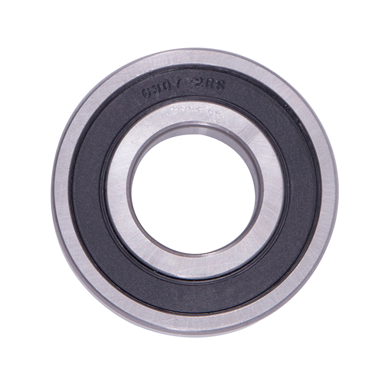
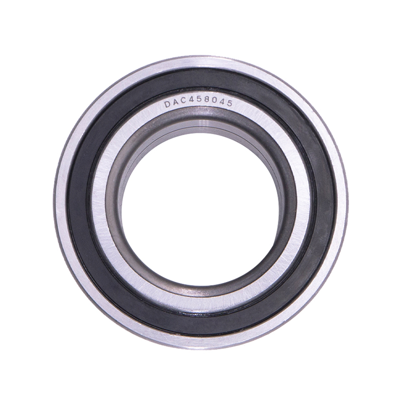
DAC387436 DAC458045 Hub Deep Groove Ball Car Wheel Bearing
-
 Spherical Bearings
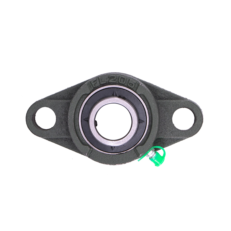
FL204 FL205 FL206 Stainless Steel Pillow Block Bearing
-
 Spherical Bearings
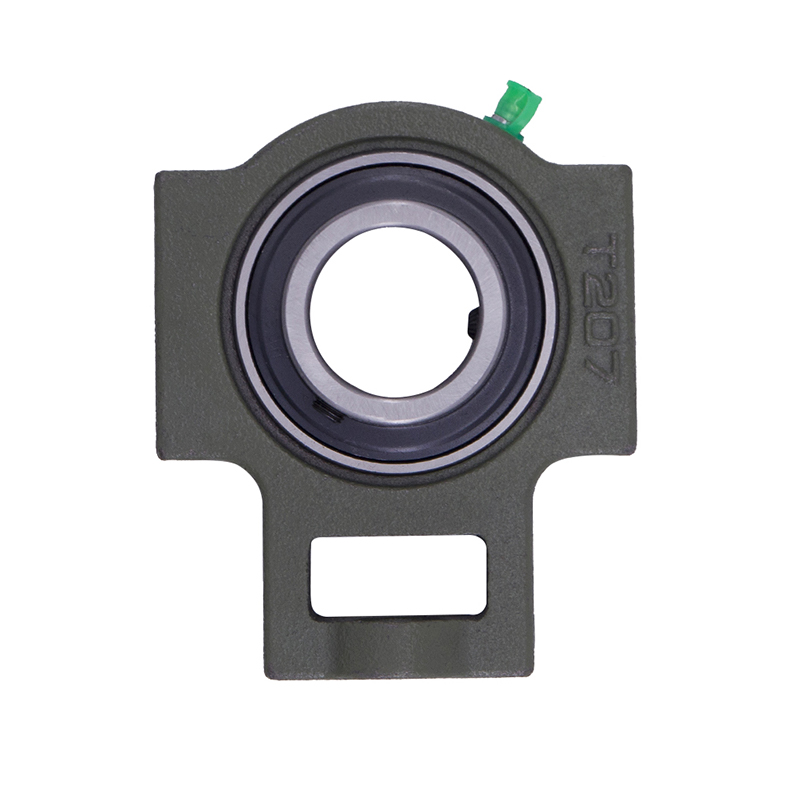
T204 T207 UC204 High Speed Insert Pillow Block Bearing
-
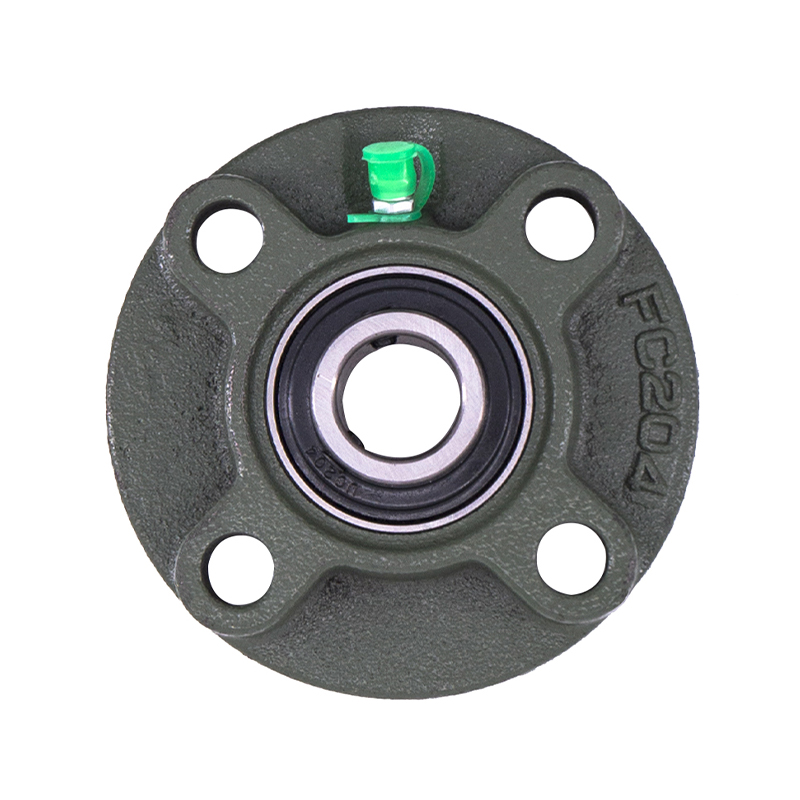 Spherical Bearings
FC204 F210 Auto Wheels Bike Pillow Block Bearing
-
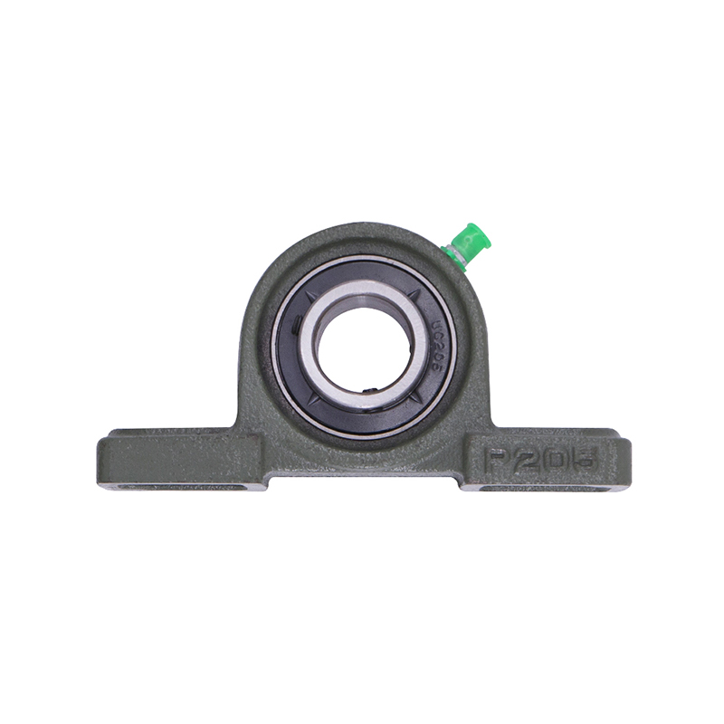 Spherical Bearings
P207 206 205 203 High Precision Wheel Pillow Block Bearing
-
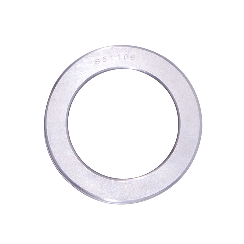 Thrust Roller Bearings
S51100 S51107 S51109 Car Wheel Plain Thrust Ball Bearing
-
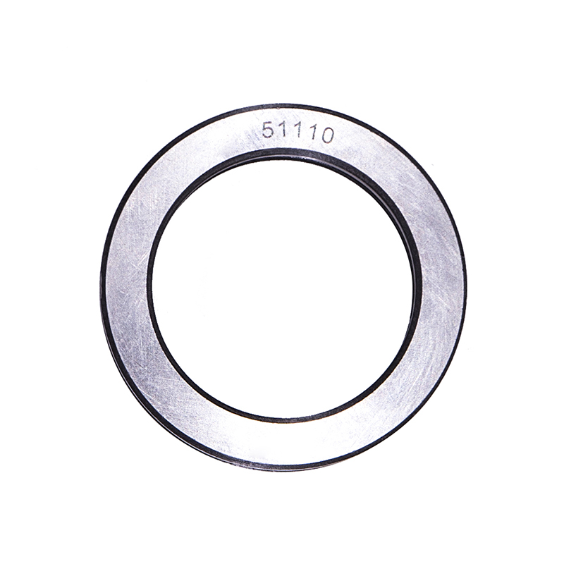 Thrust Roller Bearings
51110 51107 51104 51206 High Speed Plain Thrust Ball Bearing
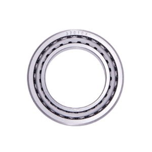
What Geometric Features Define a Tapered Roller Bearing?
Industry news-The defining characteristic of a tapered roller bearing is the tapered angle of both the rollers and the raceways. Each roller has a frustoconical shape (a truncated cone), with the larger diameter at one end and the smaller diameter at the other. The inner ring raceway (cone) and outer ring raceway (cup) are also tapered, with their surfaces angled toward the bearing centerline.
Key geometric parameters:
Contact angle (α): The angle between the roller axis and the bearing radial plane. Typical values range from 10° to 30°. Smaller angles (10–15°) favor radial load capacity; larger angles (20–30°) favor axial load capacity. Metric series bearings (ISO 355) use contact angles of 10°, 12°, 15°, 18°, 20°, 25°, and 28°.
Cone angle (β): The included angle of the tapered roller itself, typically between 12° and 32°. The roller cone angle is slightly smaller (by 0.5° to 1.5°) than the raceway cone angle to ensure contact along the roller’s full length under load.
Apex point: All roller axes, the cone raceway surface, and the cup raceway surface intersect at a common point on the bearing centerline. This apex alignment ensures pure rolling motion without sliding contact between roller ends and the guiding flanges.
Roller length-to-diameter ratio: For most tapered roller bearings, roller length is 1.0 to 1.5 times the roller diameter at the large end. Longer rollers (ratio above 1.8) increase load capacity but require more precise manufacturing to avoid skewing.
Interchangeability system: Tapered roller bearings follow the ISO 355 system or the inch-based AFBMA (Anti-Friction Bearing Manufacturers Association) system. Metric bearings are designated by series (e.g., 302, 303, 313, 322, 323). The same cone and cup from different manufacturers within the same series are interchangeable, allowing mixed sourcing.
Load Capacity and Stiffness Characteristics
Tapered roller bearings carry combined loads by resolving radial and axial forces into normal forces on the raceways. The ratio of axial to radial load capacity is determined by the contact angle.
Basic dynamic load ratings (C) and static load ratings (C₀):
|
Bearing Series |
Bore Diameter (mm) |
Contact Angle (degrees) |
Dynamic Load Rating C (kN) |
Static Load Rating C₀ (kN) |
Limiting Speed (grease, rpm) |
|
30204 |
20 |
14 |
28.5 |
30.0 |
9,000 |
|
32206 |
30 |
16 |
56.0 |
63.0 |
7,000 |
|
31308 |
40 |
28 |
68.0 |
78.0 |
4,500 |
|
32310 |
50 |
18 |
135.0 |
160.0 |
5,000 |
|
33116 |
80 |
12 |
165.0 |
220.0 |
3,200 |
Load-life relationship: The basic rating life (L₁₀, in millions of revolutions) for a tapered roller bearing follows L₁₀ = (C/P)^(10/3), where P is the equivalent dynamic bearing load. The exponent 10/3 (approximately 3.33) applies to roller bearings; ball bearings use exponent 3. For example, a bearing with C = 100 kN under P = 50 kN gives L₁₀ = (100/50)^(3.33) = 2^3.33 ≈ 10.5 million revolutions.
Stiffness properties:
- Radial stiffness: 200–600 N/μm for medium-sized bearings (80–120 mm bore)
- Axial stiffness: 400–1,200 N/μm (typically 1.5–2.5 times radial stiffness)
- Tilt (moment) stiffness: 5–20 Nm/arc-minute
Stiffness increases with preload. Applying 100–200 N axial preload to a pair of opposed bearings (face-to-face or back-to-back arrangement) increases axial stiffness by 30–60% compared to zero preload, but reduces fatigue life by 15–25% due to increased contact stress.
Load distribution: Under pure radial load, only 30–50% of rollers carry the load due to internal clearance. Under combined loads, load distribution shifts toward the roller set on the compression side. The maximum roller load can reach 2.5–4.5 times the average load per roller. The inner ring raceway contact stress at maximum load typically ranges from 1,500 to 2,500 MPa for steel bearings operating within design limits.
Materials, Heat Treatment, and Precision Grades
Ring and roller materials:
- Standard steel: SAE 52100 (AISI 52100) or DIN 100Cr6. Through-hardened to 60–64 HRC. Contains 1.35–1.60% chromium and 0.95–1.10% carbon. Maximum service temperature with standard heat stabilization: 120°C.
- High-temperature steel: SAE 4320 or 8620 case-hardened steel. Surface hardness 58–62 HRC to 1–2 mm depth; core hardness 30–40 HRC. Operating temperature up to 200°C.
- Stainless steel: AISI 440C (martensitic) for corrosion resistance. Hardness 56–60 HRC. Lower load capacity (C reduced by 15–25% compared to 52100).
Ceramic rollers (silicon nitride, Si₃N₄) for hybrid bearings: Density 3.2 g/cm³ vs. 7.8 g/cm³ for steel, allowing 30–50% higher speed. Cost 5–10 times steel.
Heat treatment sequence for 52100 steel:
Spheroidize annealing (760–800°C) – softens for machining
Hardening (820–860°C, oil quench) – achieves 63–66 HRC
Tempering (150–180°C, 2 hours) – reduces to 60–64 HRC
Stabilizing (120–150°C, 2–4 hours) – relieves grinding stress
Sub-zero treatment (-70 to -80°C) optional – converts retained austenite (5–10% down to 1–2%), improving dimensional stability
Precision grades (ISO 492):
P0 (Normal) – General industrial use (conveyors, agricultural machinery). Bore tolerance +0/-0.012 mm for 50 mm bore.
P6 (Class 6) – Electric motors, gearboxes. Bore tolerance +0/-0.010 mm.
P5 (Class 5) – Machine tool spindles, automotive wheel bearings. Bore tolerance +0/-0.008 mm.
P4 (Class 4) – Precision spindles, aerospace. Bore tolerance +0/-0.006 mm. Raceway runout below 0.002 mm.
Higher precision grades require matched roller sets (all rollers within 0.001 mm diameter range within a bearing) and individual raceway profile correction (crowning of 0.002–0.005 mm to prevent edge stress).
Our Product//
Related Product
If you are interested in our products, please consult us
Contact Details
- Address: 1377-13 Yinhai International, Jinhua, Zhejiang, China
- Fax: 0086-0319-8544668
- Tel: +86-15215868236
+86-15833609668 - Email: [email protected]
Products
Quick Link
News Center
Mobile terminal
Copyright © Yiwu Delian Bearing Co., Ltd. ALL RIGHTS RESERVED.
