 English
 русский
 Español
-
 Wheel Hub Bearings
 -
 Wheel Hub Bearings
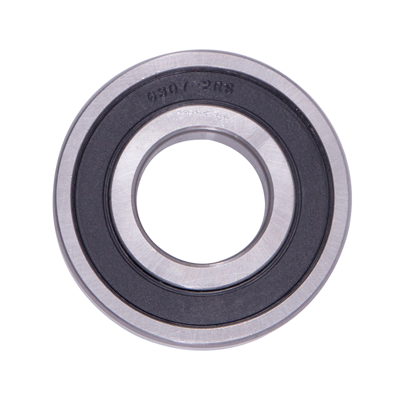
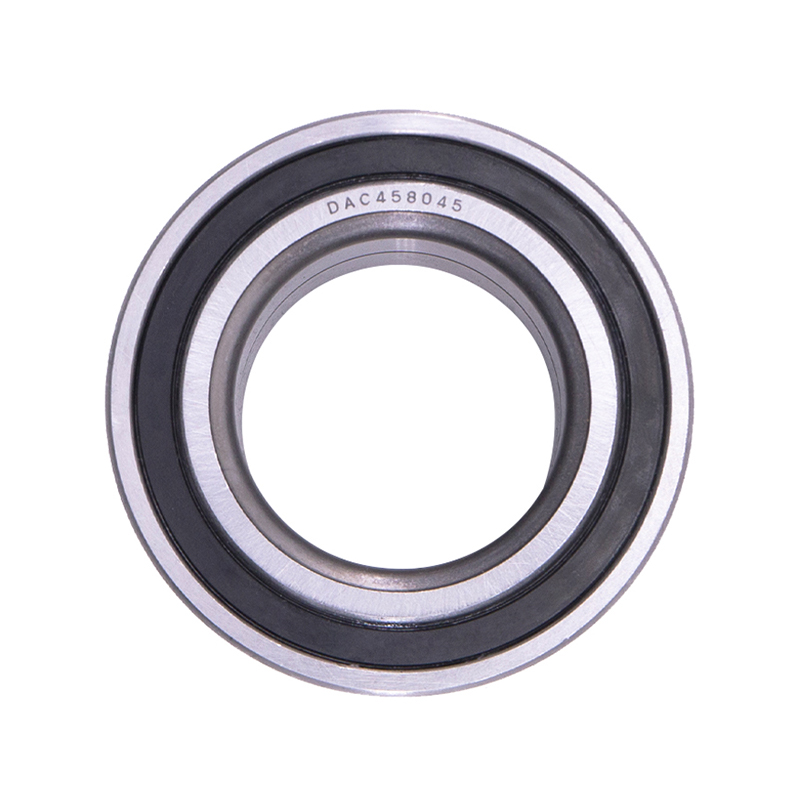
DAC387436 DAC458045 Hub Deep Groove Ball Car Wheel Bearing
-
 Spherical Bearings
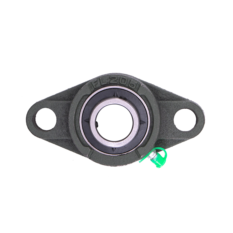
FL204 FL205 FL206 Stainless Steel Pillow Block Bearing
-
 Spherical Bearings
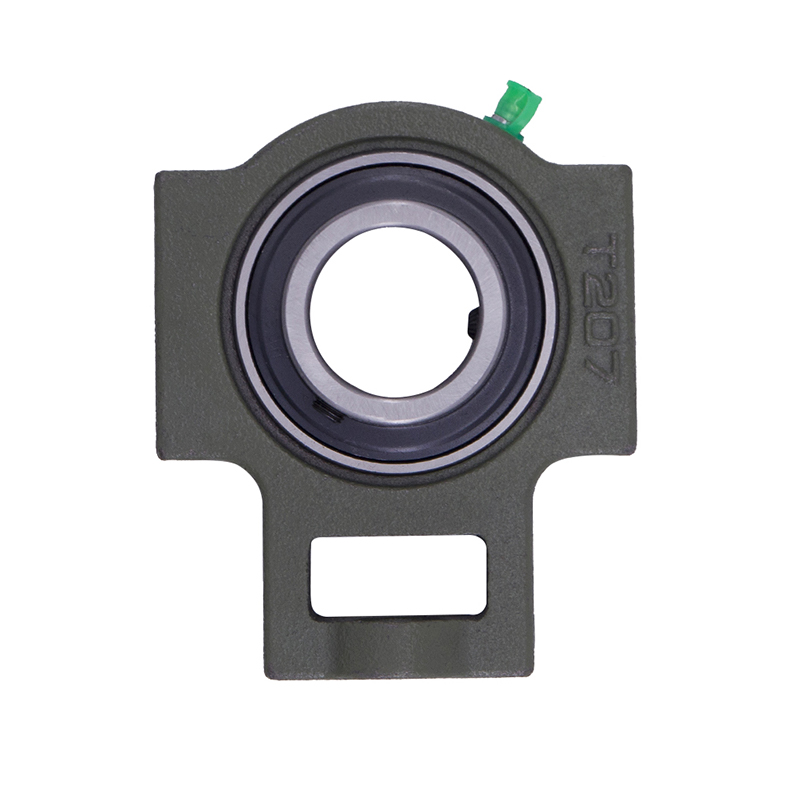
T204 T207 UC204 High Speed Insert Pillow Block Bearing
-
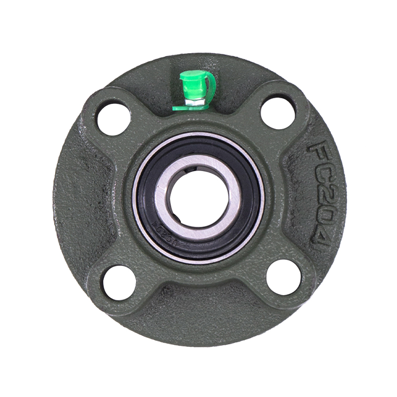 Spherical Bearings
FC204 F210 Auto Wheels Bike Pillow Block Bearing
-
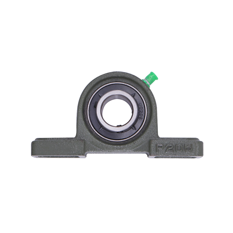 Spherical Bearings
P207 206 205 203 High Precision Wheel Pillow Block Bearing
-
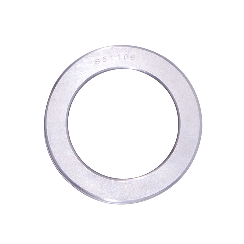 Thrust Roller Bearings
S51100 S51107 S51109 Car Wheel Plain Thrust Ball Bearing
-
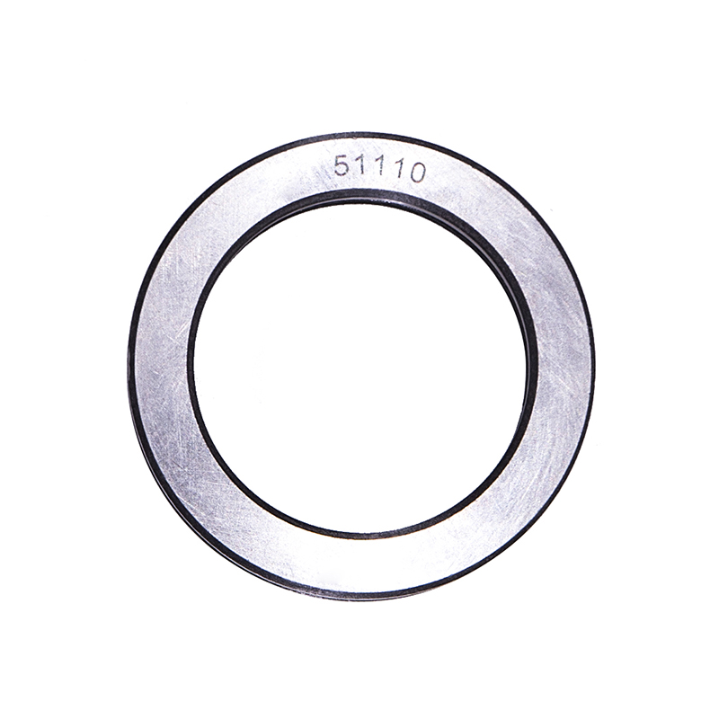 Thrust Roller Bearings
51110 51107 51104 51206 High Speed Plain Thrust Ball Bearing
How does the reduced cross-section affect load-carrying capacity compared to standard bearings?
Industry news-Load capacity scales with bearing cross-section. For two bearings of identical bore diameter, the thin wall version has smaller balls and fewer balls due to reduced raceway circumference.
- Static load rating (C0): For a standard 6204 bearing (20 mm bore, 47 mm OD), the static radial load rating is approximately 6.65 kN. A thin wall bearing of 20 mm bore with 37 mm OD has a static rating of 2.8–3.5 kN—a reduction of 47–58%. The relationship is non-linear; reducing the cross-section by 50% reduces the static capacity by approximately 70–80%.
- Dynamic load rating (Cr): Standard 6204 has a dynamic rating of 12.8 kN. The thin wall equivalent (20 × 37 mm) has 5.0–6.5 kN, representing a reduction of 49–61%. The lower rating means the thin-wall bearing achieves the same calculated fatigue life (L10 life) at a lower applied load. For a given load, the thin-wall bearing's L10 life is shorter by a factor of (Cr_thin / Cr_standard)^If Cr_thin is 50% of Cr_standard, life is 12.5% of the standard bearing's life at the same load.
- Ball size and count: A standard 6204 uses 7–8 balls of diameter 7.94 mm. A thin-wall 20 × 37 mm bearing uses 9–12 balls of diameter 3.97–4.76 mm. The smaller ball diameter increases contact stress. At a given load, the Hertzian contact stress in a thin wall bearing is 30–60% higher than in a standard bearing, accelerating surface fatigue.
What installation precautions are specific to thin wall deep groove ball bearings?
Thin wall bearings are more sensitive to installation errors than standard bearings because the thinner rings have lower rigidity. The following precautions reduce the risk of distortion.
- Housing and shaft roundness: Standard bearings tolerate housing roundness deviation up to IT5 grade (6–9 µm for 30–50 mm diameter). Thin wall bearings require IT4 grade (3–5 µm for the same diameter). Measure housing bore at three axial positions; ovality exceeding 3 µm distorts the outer ring, creating a preload variation that reduces bearing life by 30–50%. For a thin wall bearing installed in a non-circular housing (2 µm ovality), the ring deflects elastically. Radial clearance at the tight axis reduces by 30–60% of the ovality amount.
- Press-fit limits: The recommended interference fit for thin wall ball bearings is 50–60% of that for standard bearings. For a 30 mm bore bearing on a steel shaft, standard recommended interference is 8–15 µm; thin wall reduces to 4–8 µm. Excessive interference compresses the inner ring, reducing internal radial clearance. A thin wall bearing with 12 µm interference (instead of 6 µm) loses 60–80% of its initial radial clearance. If initial clearance was 10 µm (C3 fit), residual clearance becomes 2–4 µm, causing the bearing to operate under preload and generate heat. Operating temperature rise from 25°C to 60°C in such a bearing can close the remaining clearance entirely, leading to seizure.
- Mounting force application: Press forces must be applied to the ring being mounted—never through the rolling elements. For thin-wall bearings, the recommended maximum press force is 30–40% lower than for standard bearings. For a 40 mm OD thin-wall bearing, maximum force on the outer ring is 2–3 kN; exceeding this value can permanently distort the ring, creating a waviness of 0.5–1.0 mm amplitude. The distortion reduces uniformity of ball loading, increasing peak contact stress by 50–100%. Use a straightening sleeve (sized to contact 80–90% of the ring circumference) to distribute force evenly.
How does raceway groove depth affect axial load capacity in thin-wall designs?
The "deep groove" designation indicates that the raceway extends below the bearing’s pitch circle sufficiently to allow angular misalignment and axial load accommodation. In a standard deep groove bearing, the groove depth (distance from the raceway bottom to the outer ring inner surface) is approximately 25–30% of ball diameter. For a 7.94 mm ball, groove depth is 2.0–2.4 mm. In a thin-wall deep groove bearing, the same ball diameter cannot be used because the ring thickness is insufficient. Manufacturers instead use smaller balls (3–5 mm diameter) but maintain the same groove depth-to-ball diameter ratio. The axial load capacity (Fa) relative to radial load capacity (Fr) follows the relationship Fa_max = 0.5 × Fr_max for deep groove bearings. For thin-wall bearings, this ratio is maintained—a bearing with Cr = 5 kN can support 2.5 kN axial load alone. However, when combined radial and axial loads are applied, the equivalent dynamic load (P = Fr + 0.5 × Fa for deep groove bearings) is calculated identically. The limiting factor becomes the smaller ball size. Under pure axial load, the contact angle (typically 15–25 degrees in deep groove bearings) generates a radial component that must be supported by the housing. Thin-wall bearings show increased axial deflection under load: for a 5 kN axial load, a thin-wall bearing deflects 50–80 µm axially, compared to 20–30 µm for a standard bearing of the same bore. This higher compliance is acceptable in many applications, but problematic in precision positioning systems such as robotic arms or gantry stages.
Our Product//
Related Product
If you are interested in our products, please consult us
Contact Details
- Address: 1377-13 Yinhai International, Jinhua, Zhejiang, China
- Fax: 0086-0319-8544668
- Tel: +86-15215868236
+86-15833609668 - Email: [email protected]
Products
Quick Link
News Center
Mobile terminal
Copyright © Yiwu Delian Bearing Co., Ltd. ALL RIGHTS RESERVED.
